Ok, last time I promised you to put a picture of me as Dr. Zoidberg from Futurama on here. Well here it is! What do you think? ![]()
Now back to the PC model. In the post before the last one I said I will show you the Mainboard and its main features. As you can see I modelled the heat sink in pretty good detail. I did that to show you a little feature of FloEFD™V5 or better said in all of our FloEFD products. But we will get to that when the time of simulating has arrived, but first more about the Mainboard. The Mainboard was at least at the time I bought it one of the newest of it’s kind. I has all the features such as DrMOS instead of Discrete MOS which means less power consumption, lower temperature of the MOS and more stable overclocking (in my case I didn’t overclock). A lot of very nice bright blue SMD LEDs for status displays on the board and some other nice to have features such as easy BIOS update etc. The main interest when modelling the Mainboard were the heat sources with heat sinks, all the card slots such as PCI-Express, DDR3 slots, Heat Pipe and the chip socket with chip. I cannot tell what kind of chip it is but it is a quad core with 2.67 GHz. I used also all six DDR3 slots with each occupied with a 2GB RAM module. The Heat Pipe you can see is connecting the two chipsets and the third heat sink which is not connected, the one close to the USB, LAN and other ports at the back side of the Mainboard is placed on the DrMOS.
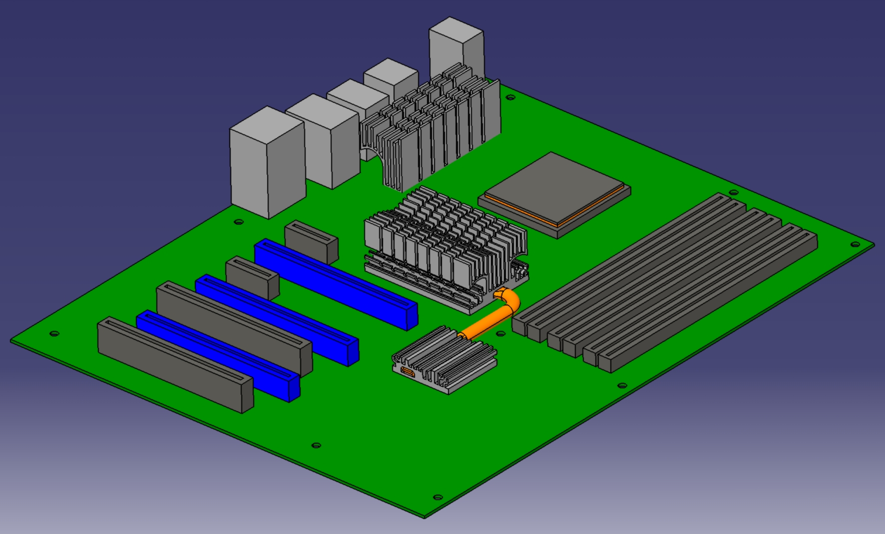
Basic Mainboards Design in Catia V5
Well this is how the Mainboards looks like with its most important features. The next thing I will do is to get some more information on the chips, for the definition of the heat sources and their material properties. So if this is done we could do a test calculation of the Mainboard without graphic card, RAM and the surrounding casing.
So, see you next time…