Author: Nazita Saye

  • Blog Post:The Chilling Facts

    I just about fell out of my chair when I heard about a new trend in using alternative or green sources of energy for data center cooling. Apparently, the good folks at HP recently released a research paper on the use of cattle waste as a source of power for cooling data centers.  No, seriously. The NY Times ran a story about the research paper and said that  “according to HP’s calculations, 10,000 cows could fuel a one-megawatt data center which would be the equivalent of a small computing center used by a bank.”

    Moo! A bit of fun with CFD and FloEFD. Image courtesy of Mentor Graphics.

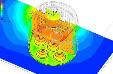
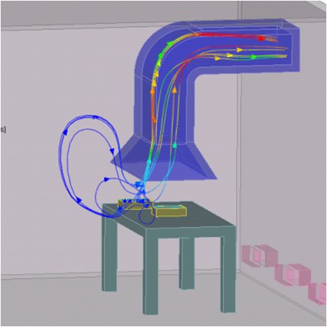
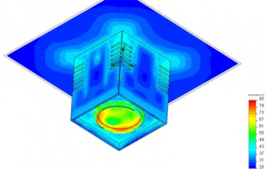
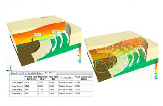
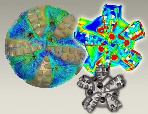
    Moo! A bit of CFD fun with FloEFD. Image courtesy of Mentor Graphics.

    Now I don’t know if anyone is seriously thinking about using biogas at this stage but I do know that data center cooling is a hot (pardon the pun) topic. Up until a few years ago, data center cooling costs were not something organizations worried about. The cost was rolled up under facilities and as long as the data center got enough power and cooling no one really fussed about the cost. But then the cost of buying electricity shot up drastically and the rules of the game changed. As a result, IT managers realized that they needed to do something a bit more sophisticated than “shirt-sleeve” management.

    There are a lot of resources out there about why simulation can help IT managers rein in the challenge of data center cooling – for example, we’ve got a couple of on-demand presentations titled: CFD in the Data Center: It’s Not About the Hall and Learn How to Reduce your Data Center Running Costs. But if you’re interested in learning about how an organization has successfully leveraged simulation (and all the gory details) please join us for an upcoming presentation titled: The Chilling Facts in Data Center Design. The presentation will take place on June 16 and you can sign-up for it here. Now I know most of you are mechanical design engineers who don’t deal with data centers so I’d appreciate it if you were to spread the word about the presentation to your IT departments. Anyway, our guest presenter for this session is Stuart Walker who is the Worldwide Facilities Critical Infrastructure Manager at Mentor Graphics. Stuart (who is an IT guy as opposed to a CFD specialist), will give us all a behind-the-scenes look at how Mentor Graphics manages our data centers around the world. Having met Stuart in person recently, I have a new appreciation for what IT managers in a similar role do across the world. Besides, this is a great chance to meet with someone who not only understands the pains associated with managing data centers but can also share firsthand knowledge of how simulation has made his life a bit easier. I really hope you can join us — it’s going to be a good session.

    Until next time,
    Nazita

  • Blog Post:Using LED Lights for Data Transmission

    I’m what you call a voracious reader. I read about a wide range of topics. I prefer to read about gadgets and advances in technology but keep an eye on pretty much everything — I’ve even been known to read my husband’s Triathlete’s World magazine (not that there is ever a danger of me wanting to do a tri … I just like knowing what’s going around me in the world). Anyway, last week I heard about a new advancement in LED technology. It seems that the good folks at Boston University and the Chinese Academy of Sciences have been very busy developing technology that lets you use LED lights to transfer data. I know what you’re thinking … we already have wireless devices and Bluetooth which seem to do the job just fine. But then we’d be missing the point. Think about it: you need to illuminate office spaces anyway so why not use the same device to network PCs and print documents? It’s a great green initiative if you ask me.

    TERALED® offers combined thermal and radiometric/photometric characterization of high-power LEDs, either as a stand-alone optical measurement system or as an add-on to T3Ster.

    TERALED® offers combined thermal and radiometric/photometric characterization of high-power LEDs, either as a stand-alone optical measurement system or as an add-on to T3Ster.

    LED lights use a lot less energy than their conventional counterparts. They last longer (the useful life for white LEDs can range from 6,000 hours to more than 50,000 hours) and they are cheaper to run. So the cost to the environment and to the pocketbook is a lot less. The only issue with them is heat. LED lights give off 91% of the energy they consume as heat and excess heat directly affects bulb output/useful life. Therefore, thermal management should be a critical factor during the design stage. We have already touched upon several resources for the design engineer working on LEDs covering simulation and LEDs, namely a whitepaper named Solving the System-Level Thermal Management Challenges of LEDs and an on-demand presentation titled: Design for Longevity in Your Power LED Products. But what we haven’t talked about is physical testing of LEDs.  Physical testing of LEDs can be very helpful because simulation results are only as good as the data used. So accessing accurate measurements to use as source input for simulation is extremely valuable.

    If you are interested in physical testing of LEDs, then it might want to read When Designing with Power LEDs, Consider Their Real Thermal Resistance. The whitepaper briefly shows why the recommendations of JEDEC JESD51 and CIE 127-2007 should be combined to obtain more accurate results. I’m sure you’ll find it helpful. I should also point out that we’ll be adding a few educational sessions on hardware testing soon so if you’re interested in the topic, please check with our events page on a regular basis.

    Until next time,
    Nazita

  • Blog Post:¡Arriba! ¡Arriba ¡Ándale! ¡Ándale!

    Let’s see a show of hands. How many of you know what I’m talking about? Yes, this was the call to action for Speedy Gonzales, the fastest cartoon mouse (and before the lawyers get involved, Speedy Gonzales and Looney Tunes are trademarks and or trade names of Warner Brothers. All rights reserved). A direct translation of it means: Up! Up! Go on! Go on! And he’d usually yell it out before speeding off to his next adventure. I can still hear myself reciting it when I drove my very first sports car on the freeway during the early morning hours oh so many moons ago.

    Now I chant it under my breath when I see Concurrent CFD in action. This type of simulation software is named Concurrent because CFD is fully embedded in CAD; as a result, you can conduct fluid flow and heat transfer analysis throughout a product’s design process. When you’re ready to analyze your new model, you simply prepare it for analysis right there and then inside CAD without transferring your data to another software or person. There’s been a fair amount of press on it lately so I won’t go into too much detail here. But the reason why Concurrent CFD reminds me of Speedy is that Concurrent CFD can reduce simulation time by as much as 65 to 75 percent in compare to traditional CFD tools. ¡Ándale! ¡Ándale!

    Analysis results on an LED light. Image courtesy of Voxdale.

    Analysis results on an LED light. Image courtesy of Voxdale.

    While all markets and products are time sensitive to a certain degree, the electronics market seems to be an extremely fast moving one.  Every day we are bombarded by ads showcasing the latest/newest/shiniest mobile phone. TVs are getting bigger and thinner by the hour. In short, time is of essence for companies developing any electronic product. So it would be helpful to do thermal validation and optimize airflow as quickly as possible. If you’re involved in electronics design and are interested in how Concurrent CFD can help, then I’d like to invite you to the Concurrent CFD for Electronics Cooling Applications online presentation. During this 45-minute presentation Travis Mikajaniec will give you a bit more background information on Concurrent CFD and show you how to take advantage of it to make your life a whole lot easier. Hope to see you there.
    Until next time,
    Nazita

  • Blog Post:Not Another Volcano Story…

    After a week of uncertainty, the skies above Europe have finally opened (albeit slowly) to air traffic. Thanks to this pesky plume of volcano ash from Iceland, all of Europe has come to a complete standstill. At a micro level, I have been enjoying the quiet — no jet engines screeching overhead every few minutes.  At a macro level, this couldn’t have happened at a worst time for a recovering world economy.  According to the Daily Telegraph yesterday, more than 17,000 flights to and from the European airspace had been canceled and it is estimated that the airlines have lost about $1.7 billion.  The same publication cited today that the travel ban has cost the economy £1.6 billion.

    Now I know that the powers that be have our safety in mind. After all, the issue isn’t just visibility. The real problem has to do with the small fragments of volcanic glass being spewed in the air.  If I understand it correctly, this volcanic ash is not only abrasive but also so fine that it can get into all sorts of crevices, jam engines and mess with electronic components.  In an article on yahoo.com yesterday titled “To fly through ash or not?”, the writer cited the case of a Boeing 747 which flew through volcanic ash over Alaska back in 1989. All four engines failed and the plane dropped 2 miles in 5 minutes. Talk about a white-knuckle ride.

    Use CFD to understand complex flow fields including exhaust. Image courtesy of Mentor Graphics.

    Use CFD to understand complex flow fields including exhaust. Image courtesy of Mentor Graphics.

    So I thought this would be a good topic for our discussion today.  No… I’m not going to talk about using mechanical CFD to simulate volcanic eruption. Instead we can talk about something a bit more commonplace — all the other types of situations where we have little particles floating in air contaminating the local environment ie exhaust from chimneys, factories and ship diesel engines.  Simulation can be an invaluable tool for understanding complex flow fields. For example, FloEFD can simulate particles floating in air including fine ash as small as 6 microns in diameter. So with the help of FloEFD, you could better understand the complexities of fluid flow in designs – including understanding where all the dust settles (so to speak) so you can start clean-up operations.  If you’d like to learn more about how CFD can help visualize and understand flow fields, please watch this short on-demand presentation titled: Simulating and Optimizing Flow Fields.

    Now I hear the airports around London will be opening up soon so I’m going to dash home, sit in my garden in the sun and enjoy the quiet for a few more hours.
    Until next time,
    Nazita

  • blog post:Mission Impossible: Finding 100W Light Bulbs

    I don’t like dark rooms –it’s probably because I’ve lived in California most of my life so I’ve gotten used to having lots of ambient daylight.  My heart sinks when I walk into a room in the middle of the day and it’s darker than a cavern. The guys in the office always know when I’m in the building because I flip the light switches as I walk through the building.  Now let me make this clear… I don’t turn on the lights when there’s plenty of sunlight and I always turn the lights off when I leave the room (that is if I’m the last one leaving the room).

    Anyway, the lighting fixture in our living room can fit three 100W lights and over the weekend one of the light bulbs unceremoniously fizzed out. Not a big problem because normally all I have to do is go to my trusty supply cabinet in the kitchen, find the right light bulb and replace the dead one. Unfortunately, we didn’t have any 100W light bulbs anywhere in the house– I had conveniently forgotten that the European Union had put a ban on the manufacture and import of them. You can’t find any of these contraband lights (including the 75W ones) in the shops although you can still buy them online (at least until the supplies run out).

    CFD analysis results on an LED light. Image courtesy of Voxdale.

    CFD analysis results on an LED light. Image courtesy of Voxdale.

    I understand why the EU is pushing consumers towards more energy efficient alternatives.These light bulbs which have been lighting our homes for 100 odd years aren’t the most energy efficient.  But I’m not a huge fan of those fluorescent low-energy lights (the light just doesn’t look right and they flicker). So it’s a good thing that there are other alternatives – among them LED lights. The useful life for an LED can range from 6,000 hours to more than 50,000 hours. To put that in perspective, good ol’ incandescent bulbs have a life of 2,000 hours. But LEDs run pretty hot; therefore, thermal issues need to be considered and dealt with during the design process. If I understand it correctly, 75% to 85% of the energy used to drive LEDs is converted to heat and therefore must be conducted from the LED die. As the leaders in thermal simulation, we have many customers who use simulation in their LED design efforts. Among them is a Belgian engineering consulting firm named Voxdale. The team at Voxdale have designed several LED lights for their customers and have gotten the design process down to an art-form — they solve power LED thermal management problems in just one day!

    In a conversation with the president of Voxdale, Koen Beyers, he mentioned that one of their customers, a lighting system manufacturer, built a prototype of a new design and discovered that the temperature of the LED rose above its maximum operating temperature rather quickly. Because the manufacturer wanted to get their product to market quickly, they didn’t have the time to optimize the thermal design the traditional way (modify and test the prototype multiple times). So the team at Voxdale solved their problem in under one day. Considering how quickly the LED market moves, any time saved in the product design process is an advantage. Anyway, if you’d like to read more about how Mr. Beyers’ team solved this LED thermal problem, please click here.

    And if you’d like to learn more about solving thermal issues of LEDs, please download a copy of this whitepaper:  Solving the System-Level Thermal Management Challenges of LEDs This white paper describes the use of CFD for LED lighting products. CFD simulation helps manufacturers optimize the design of heat sinks and other parts of the luminaire to produce low-cost, high performance products.  Happy reading!

    Until next time,
    Nazita

  • blog post:Living in a Wireless World

    I love gadgets but I hate cables – they make things so untidy. As a result, anything that can go wireless in our house has – even our light switches are on remote control. I used to think this was just plain silly when we were going through the retrofit until I realized I could turn off the kitchen lights from the comfort of our sofa. I’ve only used this “power” once but I tell you knowing that I can do it any time I wanted is priceless!

    Wireless gadgets are everywhere around us … PDAs, game controllers and mobile phones. Looking around our living room I can see 9 wireless devices (and that’s just one room). We are so used to relying on these devices that we no longer stop to think about what goes into making sure those devices work when you really need them. Ok so I won’t be in a world of pain if my wireless PS3 controller stops working in the midst of a Tekken fight tournament. But I could be in real danger if my car breaks down on the freeway and I can’t call for help because my mobile phone has stopped working due to interference from an outside source. Have you even tried finding a landline phone anywhere lately?

    Thankfully there are mobile/wireless device manufacturers who do think about these kinds of issues. Normally, in this blog we talk about all matters relating to fluid flow and thermal but I thought it would be nice to expand the realm for this week to electromagentic interference shielding (EMI) as well.

    Image courtesy of Laird Technologies

    Laird Technologies’ Thermal Interface Material (TIM), Board Level Shield (BLS) and Heat Sink. Image courtesy of Laird Technologies

    Due to the reduction in electronics form factors and the need to include more and more radios into each device, many OEMs have started to combine EMI and thermal solutions into single assemblies. As expected, this combination introduces additional complexities in the thermal design process such as the need for multiple layers of thermal interface materials whose performance interacts with each other. Most recently, one of our clients, Laird Technologies, had a project encompassing just such a scenario. Laird Technologies designs and manufactures customized, performance-critical products for wireless and other advanced electronics applications. The company is a global market leader in EMI shielding, thermal management products, mechanical actuation systems, signal integrity components, and wireless antenna solutions, as well as radio frequency (RF) modules and systems across a wide variety of industries including IT/telecommunication, medical, automotive, consumer electronics as well as military/aerospace.

    Most recently the Laird Technologies engineering team worked with an OEM customer on a custom solution consisting of a printed circuit board with a heat source and an EMI shield consisting of a metal plate that also serves as a heat spreader. The heat source is separated from the EMI shield by a layer of thermal interface material. The heat sink is mounted to the EMI shield and separated from it by another layer of thermal interface material. As you can see it is a complex design. As a result, many design parameters can be modified thus increasing the number of design alternatives that must also be considered in an effort to achieve an optimized solution.

    Shahi Riaz, Thermal Develoment Engineer at Laird, used FloTHERM CFD simulation software to learn more about the performance of their initial concept. The first model allowed the heat source package temperature to exceed the maximum value of 90° C which was above specifications. So Mr. Riaz used FloTHERM’s design optimization functionality which enables the software to automatically vary parameters such as the number of heat sink fins, fin thickness, base thickness and more. One of the parameters considered was cost which was applied implicitly by setting absolute limits on particular variables. Through this process Mr. Riaz explored the entire design space and reduced the package temperature by 13° C and brought the device within accepted design guidelines. What really made me stand up and notice was the fact that the design was optimized in only a few days compared to the weeks it would have taken to run iterations while changing one variable at a time. But we’re not done yet! When the hardware prototype was built, its thermal performance closely matched the simulation predictions. And that’s what we like – fewer respins and faster design translates into higher productivity and cost savings for everyone involved. BTW, the thermal/EMI solution is now in manufacturing and the customer feedback is very positive.

    There’s a lot more to this story so if you’d like to read more technical details about Mr. Riaz’s design as well as learn more about Laird Technologies please follow this link.

    Until next time,
    Nazita

    PS. Happy Easter everyone!

  • blog post:Leaky Valves May Delay Space Shuttle Launch

    I remember watching the first space shuttle launch back in 1981.  And almost 29 years later I still remember the sense of awe I felt when watching it take off. It felt like the whole country collectively held its breath and exhaled when it landed safely a few days later. It was a sight to behold and for the first time in my life it made me realize that Sci-Fi in this case was not fiction anymore.  Over the years I’ve seen many other majestic launches and the tragic loss of the Challenger and Columbia shuttles.  Sad days …

    So when you see news stories about a shuttle having technical problems, you take notice. Over the weekend, I ran across a story about how Discovery’s upcoming launch may be delayed due to a valve problem in the shuttle’s thruster systems.  They believe the issue relates to two important isolation valves – they are either leaking or stuck open (when they should be closed). Apparently the isolation valves can be closed manually which is good news but they still need to fix this issue if the shuttle is to take off on schedule (and without any problems).

    When I read the story the first thought that came to my head was wow… a multi-million dollar project has come to a complete standstill due to a technical glitch in a valve.

    Visualizing flow through a valve (this valve is not from the shuttle!).

    Visualizing flow through a valve (this valve is not from the shuttle!).

    Now I don’t know the details of the valve problem but I do know that valves of all shapes/sizes are around us fulfilling critical tasks such as in fuel delivery systems, in water treatment/processing plants, in medical equipment etc. So making sure valves meet their design function is important. But many organizations are still relying on good ol’ engineering know-how to design valves.  Unfortunately what you don’t see with the naked eye could prove disastrous (whether it’s missing product launch dates, manufacturing issues, or even delay customer delivery). That’s why if you are dealing with valve design, I would like to invite you to watch this short on-demand presentation titled: Flow, Pressure, Cavitation … Use X-Ray Vision to Avert a Design Disaster. The 40-minute presentation covers the typical challenges an engineer faces when designing flow control devices and it’s a good primer for identifying and fixing valve design issues with CFD.

    I hope you find the presentation helpful.

    Until next time,
    Nazita

  • blog post:It’s Spring (almost)

    Before I moved to the UK, I never gave much notice to the coming of spring. After all, in Southern California where I lived most of my life, there was hardly ever any change between the four seasons. But now, I start counting the days until spring starting on January 1 and relish every minute of sunlight that shines through the clouds past 6 PM.

    For the past week or so we’ve had glorious weather in London. Bright blue skies, warm (well warmish) sun and temperatures hovering around 11 degrees C (very low 50’s F). After a very cold winter, this “heatwave” (and I use the term very loosely) has resulted in people shedding layers and layers of sweaters/coats/scarves to run around in T-shirts and shorts. And if you’re like me this time of year starts you off on a massive spring-cleaning effort. Windows get opened so you can get fresh air through the house and you clean the muck that has built-up during the winter from windows and doors.

    And at work, I do the same thing like clockwork every spring.

    Give your analysis process a good cleaning. Image courtesy of Microsoft clipart.
    Give your analysis process a good cleaning. Image courtesy of Microsoft clipart.

    I set some time every spring to clean my desk, look through documents piled up in neat stacks and throw out what is no longer needed. At the same time, I examine my sacred cows – stuff I always do because I’ve always done them. To figuratively blow away the dust and cobwebs I ask myself: do we still need to do them? If the answer is no, then I stop doing it. If the answer is yes then I ask the second question: can it be improved at all? And invariably it always can.

    So I’d like to encourage you to do the same. Can the process of design and analysis within your organization be improved? Can you streamline your analysis process to take advantage of new concepts such as Concurrent CFD? Do you need to test so many physical prototypes or can some of them be replaced with virtual ones? Can you…?

    Yes … you can.

    Now some of you may be thinking: I’d love to do something about it but it falls outside my realm of influence. That’s ok. You can gather facts by going to websites such as ours to find out how other companies have done the same thing and sharing the information with your manager. For example, we have a series of success stories that showcase how other companies have blown away the cobwebs in their analysis process. Or you can watch a series of freely available on-demand presentations on various topics to educate yourself on the subject-matter. It doesn’t require a lot of time or effort but I can assure you that at the end of the process you’ll find a renewed sense of energy.

    Until next time,
    Nazita

  • blog post:The Next Industrial Revolution

    We are all familiar with the industrial revolution – a period where major changes in the way we did stuff (whether it was food production, manufacturing, moving from point A to point B … pretty much everything we did) impacted not only the economy but also our culture as well. So imagine my surprise when I heard on the radio that we are smack-dab in the middle of the next industrial revolution.

    responsible-design2

    Gain additional insight into how you can make your designs more efficient with CFD.

    This industrial revolution refers to the green movement. Whether or not you believe in global warming, our generation is trying to minimize its impact on mother earth. We have introduced new laws, promised to reduce our carbon footprint and generally become more responsible in the way we use the limited resources we have on hand. Regardless of which side of the green fence you sit on, who can argue with increasing efficiency so that the same tank of gas can give you more than 100 MPG especially since a full tank now costs an arm and a good portion of a leg? Or reducing the cooling requirements in a building so the equipment can operate safely while ensuring occupant comfort?

    Getting more out of the same or even fewer resources is something we talk about here in the ROI blog all the time. So I would like to extend an invitation to everyone for an upcoming free online event titled Responsible Design for a Greener Future From what I understand, if poor design decisions make it through to the final build stage, then the cost of repair is 3 orders of magnitude greater than if the problem had been identified during the initial design stage.  This online presentation will show you how computational fluid dynamics (CFD) can help reduce costs associated with design and operation in the built environment by enabling you to catch possible design flaws during the very early stages of design – when the cost of fixing issues is much lower. CFD has been used to prove data center room layouts and cooling needs, ventilation in parking structures and office buildings and even automotive and plane passenger comfort. So now, you can take your designs to the next level by making sure that your designs meet not only your design specifications but regulatory and environmental requirements as well.

    Hope to see you there.
    Until next time,
    Nazita

  • blog post:Semiconductor Package Thermal Characterization and Design as Easy as 1-2-3

    If you are involved with semiconductor packaging design, then have I got news for you.

    We just announced the availability of FloTHERM IC – a web-based tool that delivers a high level of automation to design tasks associated with full-spectrum thermal characterization and validation.

    From what I understand, a typical semiconductor thermal team spends about 60% of their time on standard package thermal characterization and design. The remainder of their time is spent on customer specific characterization. What’s neat about FloTHERM IC is that it automates the process so you can drastically reduce not only the time spent on the standard package design but also on the customer specific characterization as well.  And FloTHERM IC includes pre-verified thermal models which can reduce the risk of modeling errors. Nice.chip

    So what are the areas addressed by FloTHERM IC:

    • Full-spectrum thermal metric and compact model generation with full adherence to published JEDEC standards
    • “Package-aware” parametric design for “what-if” analysis
    • EDA tool interfacing for detailed modeling of BGA substrates for physical layout
    • Data mining of simulation data to enable optimized design time and reuse

    I should point out that FloTHERM IC uses FloTHERM CFD software as its analysis engine (the number one software of choice for thermal engineers around the world) and it uses FloTHERM PACK Smart Parts which help reduce risk of modeling errors. And FloTHERM IC has a wizard-based interface which makes using it very intuitive. For additional information about FloTHERM IC and what it can do, please follow this link.

    Since this blog is all about ROI, then let’s talk about how you can try FloTHERM IC for free. You can request a free 30-day trial version from here.  Please bear in mind that you will be using the production-version of the software so you can use it to work on your real projects — not some canned stuff. 23 of the top 50 semiconductor companies use our products so you’ll be in very good company.

    Until next time,
    Nazita

  • blog post:Gain Insight the Faster Better Way

    Double-time.  Instantaneous.  Faster than the speed of light. No… these words do not describe the speed by which I reach a conclusion (although my husband would beg to differ). These words refer to our generation wanting things.

    We want it now.

    We can’t wait. We no longer purchase a DVD online and wait for it to arrive – at a touch of a button we stream the movie and watch it immediately. Forget about websites that take too long to load – we move on to the next one faster than you can say “connecting, transferring, connecting…“. Sign a document and fax it? How very last century – send it via email and it’s made it across the world double quick time and without any danger of a paper-cut. Build multiple physical prototypes and test them to confirm the performance of the various designs?  Sure… why not. Hey, wait a second, how did that get in there?

    In this day and age of fast, faster, fastest, it is amazing that some organizations still insist on testing multiple physical prototypes instead of using computational fluid dynamics (CFD) software for simulation.  I fully understand why you’d want to test a physical prototype but surely testing multiple virtual models is the faster and less expensive option. Then once you’re happy with the results, you can build a physical prototype for final verification purposes.

    For example, Encore Drill Bits is a relatively small drill bit manufacturer. They provide oilfield polycrystalline diamond compact (PDC) drill bits. Because of the rough drilling environment for both the cutters and the bit body, the preferred bit choice for tough drilling areas has historically been the roller cone bit; however, their relative inexpensiveness is negated by the number of bits required to finish drilling a section of the well. Encore planned to develop a bit that can drill the entire section with only one bit and be rebuilt several times as this helps reduce the costs for both the operator and Encore. However, the early versions of the bit showed an erosion problem after only one or two runs. Because Encore sets its rental rates based on being able to rebuild the bits, the severe erosion affected the company’s ability to rebuild the bit cost effectively.

    FloEFD helps Encore Bits LLC solve erosion problem. Image courtesy of Encore Bits.

    FloEFD helps Encore Bits LLC solve erosion problem. Image courtesy of Encore Bits.

    Obviously, the drilling process doesn’t exactly make it easy to discover what kind of flow pattern might be causing the untimely erosion. So Encore uses CAD- embedded CFD software to optimize the PDC bit during the design phase because the time and cost required to perform CAD-embedded CFD are much lower than with conventional CFD tools. For example, it took Vince Salvo, Design Engineer for Encore Bits, only 1 day to optimize the design of the company’s F-5165D bit. The CFD simulation identified high flow areas near one blade that reduced the life of the bit.  From looking at the simulation results, Salvo gained an understanding of the problem which almost immediately gave him ideas on how to improve the performance of the design. He tried several ideas … singly and in combination and with each design iteration, he gained additional insight that helped drive steady improvements. Needless to say, the bit was introduced to the market and it is performing beautifully. If you’d like to read more about Mr. Salvo’s challenge and how he used CFD to gain insight the faster, better way, please follow this link.

    And if you’re looking for a way to do things the faster, better way, then take a look at FloEFD – the preferred software of choice for design engineers who don’t have the time (or inclination) to mess around with old school general purpose CFD tools. You can find many application examples here and quite a few on-demand presentations here.

    Until next time,
    Nazita

    PS. If you’re in the San Jose area, please stop by booth 202 at Semi-THERM  at the Hyatt Regency in Santa Clara. We’ll be showcasing our MicReD thermal characterization products. We will also have a new surprise for the engineering community. I’m not going to tell you what it is today but if you want a cheeky peek then stop by Ballroom E today at 2 PM. All I can say about it now is: it’s very cool.

  • blog post:EDN Hot 100 Award for FloEFD

    I normally don’t do posts about these kinds of things but I was really excited to hear this. Recently FloEFD was given an EDN Magazine’s Hot 100 Electronic Products for 2009 award. The Hot 100 consists of EDN’s list of “the products and technologies that in 2009 heated up the electronics world and grabbed the attention of our editors and our readers.”

    Fantastic!

    I know I’m a proud parent but FloEFD is pretty cool.  Because FloEFD is embedded in CAD, it helps users integrate the CFD process into their overall design process.  Due to its heavy integration with CAD and its underlying technology, FloEFD offers users feedback on their designs quickly. As a matter of fact, users have found that FloEFD can reduce simulation time by as much as 65 to 75% when compared with traditional CFD tools.  We call this technology Concurrent CFD.  It really is a fantastic bit of technology and it’s for a lot more than just electronics. If you haven’t had a chance to see FloEFD in action, then you may want to watch one of these short on-demand video clips — you’ll find a whole slew of products being evaluated and improved.

    And for those of you who voted for FloEFD, here’s a big thank you for making us one of the Hot 100.

    Until next time,
    Nazita

  • blog post:The Secret of Doing Fewer PCB Respins – Unveiled!

    I come across a fair bit of industry research and I read it all. Unfortunately retrieving the information from my brain can be a bit problematic because my brain doesn’t think or store information in a linear fashion. So from time to time I find myself skimming the reports again just to remind myself of the information. These sessions are usually littered with my yelps of “that’s right” and “oh that’s interesting” (no doubt much to the annoyance of everyone else sitting around me in our open office).   And sometimes when the information is really juicy I read it out loud to no one in particular and inevitably start a conversation chain reaction.

    One of the conversation chain reactions was about PCB respins. Now my division has quite a pedigree in matters relating to electronics cooling so we have a lot of experts who’ve been there, done that and so to speak have not only read the book but in all likelihood they wrote it! But even this bit of information made everyone stand up and listen.

    Users of Mentor Mechanical products respin their designs fewer times. Image courtesy of Aberdeen Group.

    Users of Mentor Mechanical products respin their designs fewer times. Data courtesy of Aberdeen Group.

    According to a 2007 Aberdeen Group survey, our customers (Mentor Mechanical Analysis customers) are 5 times more likely to respin their design only once with the rest of the industry averaging nearly 3 respins per design. So what this says to me is by using software tools such as FloTHERM and FloTHERM PCB, users can significantly reduce the number of design respins by dealing with mechanical thermal issues with simulation early on and get the product out to market faster (and less expensively if I might add). Wow … now that’s a secret I don’t mind spilling the beans on!

    !–content–>

    If you are a mechanical engineer and are curious about how you can reduce PCB respins, then I’d like to invite you to attend a free presentation titled Reducing PCB Respins. The presentation will take place on Wednesday February 24 and is open to everyone. The speaker is one of our product managers, Byron Blackmore. He is one of the electronics cooling gurus I mentioned earlier so he really knows what he’s talking about.  I for one am really looking forward to hearing him speak on the topic because I always learn something new whenever I speak with him.  Hope to see you there.

    Until next time,
    Nazita

  • blog post:The recession is over, finally

    I’ve started listening to talk radio on my way to work – the conversation keeps my brain active during the gruelling stop-and-go traffic of London. Anyway, Tuesday’s news was one we had been waiting 18 months to hear — the worst recession to hit England since the 40s was finally over. What really surprised me was that we were the last of the Western nations to dig ourselves out of the global recession – I guess better late than never. While that is most certainly welcome news, most executives around the world are remaining cautious about throwing their doors wide open and spending with abandon. According to an annual PricewaterhouseCoopers report released earlier yesterday most of the firms they surveyed are planning on further reducing their costs while improving efficiency. And if you’re wondering, this survey was quite comprehensive – it included 1,198 chief executives from 52 countries and was conducted late last year.

    And you know what? I think that is quite sensible.

    Where do you fit in in terms of your physical prototype testing? Source: Aberdeen Group.

    Where do you fit in in terms of your physical prototype testing? Source: Aberdeen Group.

    Reducing costs and improving efficiency should be in our thoughts at all times regardless of the state of the economy. So what are some of ways we can reduce costs (as they relate to engineering)? For starters, we could reduce the costs associated with physical prototype testing by doing fewer of them. According to an Aberdeen Group study conducted in 2006, depending on the complexity of the product being designed, companies can spend anywhere between $8,000 and $1.2 million on creating and testing physical prototypes and this process can average between 13 and 99 days! Not an insignificant amount time or money. Now that was a couple of years ago so considering inflation I’m sure the cost has increased even more. BTW I should point out that I’m not advocating getting rid of physical prototype testing in its entirety or for all products … I’m just saying we could perhaps reduce the number of them and still ensure the appropriate safety and quality levels required.

    How can we improve efficiency at the same time? While this may seem like an oxymoron, the way I read it is this: by improving efficiency, you can do more in the same time frame and you can do it using fewer resources.  One of the ways we can achieve this objective, is to use simulation. By simulation I mean all kinds of simulation – be it stress analysis, fatigue or CFD. There are plenty of companies (of all shapes and sizes if I may add) that have not only met this two headed beast, but they have slain it: Encore Drill Bits, Azonix, and Voxdale.

    In short, it is always good to exercise caution when spending funds. But if you are sitting on the bench wondering whether you should dip your toes in, then call a handful of vendors and ask them if they would let you evaluate their tool. BTW all vendors have a slick demo but the truth lies in whether they can take your geometry, prepare it for analysis and show you the results within a reasonable time frame.  I’d say you’ve got nothing to lose by taking a closer look at the technology. You may even find a pretty cool tool that can not only pay for itself but make you even more competitive in a (still) tough economic climate.
    Until next time,
    Nazita

  • blog post:May the force be with you

    Don’t worry… I’m not going Sci-Fi on you. I’m talking about reaction forces. What do I mean by reaction forces? Well, when there is a relative motion between a solid object and a surrounding fluid, a force will be placed on the solid due to the pressure variation over the surface of the solid. This force is caused by the change in speed and direction of the fluid. For example, we see reaction forces in action when water flows through a pump.

    Reaction forces on a rear-wing of an Indy race car. Image courtesy of Voxdale.

    Reaction forces on a rear-wing of an Indy race car. Image courtesy of Voxdale.

    Now predicting force or pressure distribution on a surface should be a key design decision factor in the design of any system in which a moving fluid can cause product reliability, stability and usability issues (I’m including safety under this category because unless it is safe to use, it isn’t really usable now is it?).  Force prediction can be used to optimize the geometry or to determine what’s required to support the said structure.

    Several methods have been used by manufacturers for predicting pressure forces but I always say the one that offers the best combination of speed, affordability and accuracy is Computational Fluid Dynamics (CFD) software. CFD has proven its efficacy for handling these kinds of problems – there are plenty of application stories and customer testimonials out there. For example, a team at Watts Industries Netherlands deals with design issues relating to backflow prevention devices and automatic control valves for domestic, commercial and industrial uses of water. They need to be extremely careful because contamination of drinking water could prove disastrous. So they use CFD software to test their designs. And to further verify the results, they create and test physical prototypes. They have been able to obtain exactly the same results from their chosen CFD software as their test rig; thus allowing them to deploy their products to the field with increased confidence. According to Rene Aarntzen, the R&D Engineering Manager at Watts Industries, “For the past year we have found exactly the same results from FloEFD and our test rig. That’s important because maybe in a few years, after we’ve built an extensive library of results, then we won’t need to build and test physical prototypes anymore.” Personally as a manager, I find any opportunity to save cost without sacrificing quality, safety or purpose a tall cool drink of water on a hot summer day!

    If you are interested in learning more about how to harness reaction forces or to optimize your designs, I would suggest your attending our upcoming online presentation titled: Simulating and Optimizing Reaction Forces. The presenter, Nate Hanlon, is one of our consultant engineers based in the States and he has a background in the design of fans, blowers and impellers. So feel free to ask him a few questions. I’m sure he’s got some sage words of advice for everyone. And before I forget, as with all online presentations, anyone who registers for the event will be sent a link to the archived version so even if you can’t attend the meeting at the specified time, you will be able to access the presentation at your convenience after the event.

    Lastly, if you like to read more about Mr. Aarntzen’s experience at Watts Industries, please feel free to click here.

    Hope to see you at the meeting (now if I could only get the stormtrooper music out of my head, we’d be golden).
    Until next time,
    Nazita

  • blog post:Winter Woes and LED Lights

    While de-icing my car this morning, I was listening to the radio. The announcer said that we are expecting more snow in London this week. The news sent shivers down my spine but not for the reason you may think. As if the ice on the road and pedestrians jumping in front of moving cars isn’t bad enough, we may have a new problem to deal with: it seems that LED traffic lights may have a problem dealing with snow.

    Unlike their incandescent counterparts, LED traffic lights do not melt the snow that covers the  housings (in case you haven’t read about this here’s a link on Slashdot ). As a result, some cities have reported accidents where drivers have plowed into the intersection because they have been unable to tell whether they have the right of way. Now California has had a low tech solution which we’ve used for years:  if the traffic light is out, you revert to a 4-way stop sign.  But I guess not every state has this law. And while we’re on the subject London could really use this because when traffic signals go out here, you basically have to play a game of Frogger. So why am I concerned about this? For two reasons:

    1) personal – most of the traffic lights in my part of London are LED lights; therefore, the thought of having to sit at an intersection playing Frogger is not my idea of fun.

    and

    2) professional – as someone involved in the field of CFD and thermal simulation, it seems to me that this problem may be fairly easy to solve. From what I’ve heard, LEDs give off 91% of the energy they consume as heat. So it stands to reason that by creating a different heatsink you should be able to channel the heat to the right place and solve this problem. Unfortunately this solution would require a bit of retrofitting but in the grand scheme of things, it’s better than dispatching armies of people with brooms to clear the snow away …

    So if you’re a design engineer and are intrigued about using simulation to solve this problem for your organization cost-effectively, then please go here to find additional information from your thermal experts (us)!

    Until next time,
    Nazita